(My) CISSP Notes – Application development security

Note: This notes were made using the following books: “CISPP Study Guide” and “CISSP for dummies”.

Programming concepts

Machine code (also called machine language) is a software that is executed directly by the CPU. Machine code is CPU-dependent; it is a series of 1s and 0s that translate to instructions that are understood by the CPU.

Source code is computer programming language instructions which are written in text that must be translated into machine code before execution by the CPU.

Assembly language is a low-level computer programming language.

Compilers take source code, such as C or Basic, and compile it into machine code.

Interpreted languages differ from compiled languages: interpreted code (such as shell code) is compiled on the fly each time the program is run.

Procedural languages (also called procedure-oriented languages) use subroutines, procedures, and functions.

Object-oriented languages attempt to model the real world through the use of objects which combine methods and data.

The different generations of languages:

Application Development Methods

The Waterfall Model is a linear application development model that uses rigid phases; when one phase ends, the next begins.

The waterfall model contains the following steps:

  • System requirements
  • Software Requirements
  • Analysis
  • Program Design
  • Coding
  • Testing
  • Operations

An unmodified waterfall does not allow iteration: going back to previous steps. This places a heavy planning burden on the earlier steps. Also, since each subsequent step cannot begin until the previous step ends, any delays in earlier steps cascade through to the later steps.

The unmodified Waterfall Model does not allow going back. The modified Waterfall Model allows going back at least one step.

The Sashimi Model has highly overlapping steps; it can be thought of as a real-world successor to the Waterfall Model (and is sometimes called the Sashimi Waterfall Model).

Sashimi’s steps are similar to the Waterfall Model’s; the difference is the explicit overlapping,

Agile Software Development evolved as a reaction to rigid software development models such as the Waterfall Model. Agile methods include Scrum and Extreme Programming (XP).

Scrum contain small teams of developers, called the Scrum Team. They are supported by a Scrum Master, a senior member of the organization who acts like a coach for the team. Finally, the Product Owner is the voice of the business unit.

Extreme Programming (XP) is an Agile development method that uses pairs of programmers who work off a detailed specification.

The Spiral Model is a software development model designed to control risk.

The spiral model repeats steps of a project, starting with modest goals, and expanding outwards in ever wider spirals (called rounds). Each round of the spiral constitutes a project, and each round may follow traditional software development methodology such as Modified Waterfall. A risk analysis is performed each round.

The Systems Development Life Cycle (SDLC, also called the Software Development Life Cycle or simply the System Life Cycle) is a system development model.

SDLC focuses on security when used in context of the exam.

No metter what development model is used, these principles are important in order to ensure that the resulting software is secure:

  • security in the requirements – even before the developers design the software, the organization should determine what security features the software needs.
  • security in the design – the design of the application should include security features, ranging from input checking, dtrong authentication, audit logs.
  • security in testing – the organization needs to test all the security requirements and design characteristics before declaring the software ready for production use.
  • security in the implementation
  • ongoing security testing – after an application is implemented, security testing should be performed regularly, in order to make sure that no new security defects are introduced into the software.  

Software escrow describes the process of having a third party store an archive or computer software.

Software vulnerabilities testing

Software testing methods

  • Static testing – tests the code passively, the code is not running, this includes syntax checking, code reviews.
  • Dynamic testing – tests the code while it executing it.
  • White box testing – gives the tester access to program source code.
  • Black box testing – gives the tester no internal details, the application is treated as a black box that receives inputs.

Software testing levels

  • Unit Testing – Low-level tests of software components, such as functions, procedures or objects
  • Installation Testing – Testing software as it is installed and first operated
  • Integration Testing – Testing multiple software components as they are combined into a working system.
  • Regression Testing – Testing software after updates, modifications, or patches • Acceptance Testing: testing to ensure the software meets the customer’s operational requirements.

Fuzzing (also called fuzz testing) is a type of black box testing that enters random, malformed data as inputs into software programs to determine if they will crash.

Combinatorial software testing is a black-box testing method that seeks to identify and test all unique combinations of software inputs. An example of combinatorial software testing is pairwise testing (also called all pairs testing).

Software Capability Maturity Model

The Software Capability Maturity Model (CMM) is a maturity framework for evaluating and improving the software development process.

The goal of CMM is to develop a methodical framework for creating quality software which allows measurable and repeatable results.

The five levels of CMM :

  1. Initial: The software process is characterized as ad hoc, and occasionally even chaotic.
  2. Repeatable: Basic project management processes are established to track cost, schedule, and functionality.
  3. Defined: The software process for both management and engineering activities is documented, standardized, and integrated into a standard software process for the organization.
  4. Managed: Detailed measures of the software process and product quality are collected, analyzed, and used to control the process. Both the software process and products are quantitatively understood and controlled.
  5. Optimizing: Continual process improvement is enabled by quantitative feedback from the process and from piloting innovative ideas and technologies.

Databases

A database is a structured collection of related data.

Types of databases :

  • relational databases – the structure of the relation database its defined by its schema. Records are called rows, and rows are stored in tables. Databases must ensure the integrity of the data. There are three integrity issues that must be addressed beyond the correctness of the data itself: referential integrity (every foreign key in a secondary table matches a primary key in the parent table), semantic integrity (each column value is consistent with attribute data type) and entity integrity (each tuple has a unique primary key that is not null). Data definition language (DDL) is used to create, modify and delete tables. Data manipulation language (DML) is used to query and update data stored in tables.
  • hierarchical – data in a hierarchical database is arranged in tree structures, with parent records at the top of the database, and a hierarchy of child records in successive layers.
  • object oriented – the objects in a object database include data records, as well as their methods.

Database normalization seeks to make the data in a database table logically concise, organized, and consistent. Normalization removes redundant data, and improves the integrity and availability of the database.

Databases may be highly available, replicated over multiple servers containing multiple copies of data. Database replication mirrors a live database, allowing simultaneous reads and writes to multiple replicated databases. A two-phase commit can be used to ensure integrity.

A shadow database is similar to a replicated database with one key difference, a shadow database mirrors all changes made to the primary database, but the clients do not have access to the shadow.

Knowledge-based systems

Expert systems consist of two main components. The first is a knowledge base that consists of “if/then” statements. These statements contain rules that the expert system uses to make decisions. The second component is an inference engine that follows the tree formed by the knowledge base, and fires a rule when there is a match.

Neural networks mimic the biological function of the brain. A neural-network accumulates knowledge by observing events; it measures their inputs and outcome. Over time, the neural network becomes proficient at correctly predicting an outcome because it has observers several repetitions of the circumstances ans is also told the outcome each time.
(My) CISSP Notes – Telecommunications and network security (II)

Note: This notes were made using the following books: “CISPP Study Guide” and “CISSP for dummies”.

Network Layer protocols and concepts

Routing protocols

Routing protocols are defined at the network level and specify how routers communicate with one another or a WAN.The goals of routing protocols are to automatically learn a network topology, and learn the best routes between all network points.Routing protocols are classified as static or dynamic.

static routing protocol requieres an administrator to create and update routes manually on the router. A dynamic routing protocol can discover routes and determine the best route to a given destination at any given time.

Metrics are used to determine the “best” route across a network. The simplest metric is hop count.

Distance vector routing protocols use simple metrics such as hop count, and are prone to routing loops, where packets loop between two routers.

  • RIP(Routing Information Protocol) is a distance vector routing protocol that uses hop count as its metric.RIP does not have a full view of a network: it can only “see” directly connected routers. Convergence is slow. Convergence means that all routers on a network agree on the state of routing. A network that has had no recent outages is normally “converged”: all routers see all routes as available. Then a circuit goes down. The routers closest to the outage will know right away; routers that are further away will not. The network now lacks convergence. RIP is used by the UNIX routed command, and is the only routing protocol universally supported by UNIX.RIP is quite limited. Each router has a partial view of the network and each sends updates every 30 seconds, regardless of change. Convergence is slow.

Link state routing protocols factor in additional metrics for determining the best route, including bandwidth.

  •  OSPF (Open Shortest Path First) is an open link state routing protocol. OSPF routers learn the entire network topology for their “area” (the portion of the network they maintain routes for, usually the entire network for small networks). OSPF it’s considered an Interior Gateway Protocol (IGP) because it performs routing within a single autonomous system. An autonomous system (AS) is a group of IP address uder the control of the a single Internet entity.
  • BGP (Border Gateway Protocol) is the routing protocol used on the Internet. BGP it’s considered an Exterior Gateway Protocol (EGP) because it performs routing between separate autonomous systems.

Routed protocols

Routed protocols are network layer protocols that address packets with routing information, which allows those packets to be transported across networks by using routing protocols.

IP (Internet Protocol) – IPv4 is Internet Protocol version 4, commonly called “IP.” It is the fundamental protocol of the Internet, designed in the 1970s to support packet-switched networking for the United States Defense Advanced Research Projects Agency (DARPA).

IP is a simple protocol, designed to carry data across networks.IP is connectionless and unreliable: it provides “best effort” delivery of packets. If connections or reliability are required, they must be provided by a higher level protocol carried by IP, such as TCP.IPv4 uses 32-bit source and destination addresses.

If a packet exceeds the Maximum Transmission Unit (MTU) of a network, it may be fragmented by a router along the path. An MTU is the maximum PDU size on a network. Fragmentation breaks a large packet into multiple smaller packets.

The original IPv4 networks were “classful”, classified in classes:

Class Leading
bits
Size of network
number
 bit field
Size of rest
bit field
Number
of networks
Addresses
per network
Start address End address
Class A     0     8     24     128 (27)     16,777,216 (224) 0.0.0.0 127.255.255.255
Class B     10     16     16     16,384 (214)     65,536 (216) 128.0.0.0 191.255.255.255
Class C     110     24     8     2,097,152 (221)     256 (28) 192.0.0.0 223.255.255.255
Class D (multicast)     1110     not defined     not defined     not defined     not defined 224.0.0.0 239.255.255.255
Class E (reserved)     1111     not defined     not defined     not defined     not defined 240.0.0.0 255.255.255.255

IPv6 is the successor to IPv4, featuring far larger address space (128 bit addresses compared to IPv4’s 32 bits), simpler routing, and simpler address assignment.IPv6 hosts can statelessly autoconfigure a unique IPv6 address, omitting the need for static addressing or DHCP. IPv6 stateless autoconfiguration takes the host’s MAC address and uses it to configure the IPv6 address.

Stateless autoconfiguration removes the requirement for DHCP (Dynamic Host Configuration Protocol), but DHCP may be used with IPv6: this called “stateful autoconfiguration,” part of DHCPv6.

IPv6’s much larger address space also makes NAT (Network Address Translation) unnecessary, but various IPv6 NAT schemes have been proposed, mainly to allow easier transition from IPv4 to IPv6.

Hosts may also access IPv6 networks via IPv4; this is called tunneling. Another IPv6 address worth noting is the loopback address: ::1. This is equivalent to the IPv4 address of 127.0.0.1.

Hosts may also access IPv6 networks via IPv4; this is called tunneling. Another IPv6 address worth noting is the loopback address: ::1. This is equivalent to the IPv4 address of 127.0.0.1.

An IPv6-enabled system will automatically configure a link-local address (beginning with fe80:…) without the need for any other ipv6-enabled infrastructure. That host can communicate with other link-local addresses on the same LAN. This is true even if the administrators are unaware that IPv6 is now flowing on their network.

Network Address Translation (NAT) is used to translate IP addresses. It is frequently used to translate RFC1918 addresses as they pass from intranets to the Internet.

Three types of NAT are static NATpool NAT (also known as dynamic NAT), and Port Address Translation (PAT, also known as NAT overloading). Static NAT makes a one-to-one translation between addresses, such as 192.168.1.47→192.0.2.252. Pool NAT reserves a number of public IP addresses in a pool, such as 192.0.2.10→192.0.2.19. Addresses can be assigned from the pool, and then returned. Finally, PAT typically makes a many-to-one translation from multiple private addresses to one public IP address, such as 192.168.1.⁎ to 192.0.2.20. PAT is a common solution for homes and small offices: multiple internal devices such as laptops, desktops and mobile devices share one public IP address.

Other network layer protocols

  • ICMP (Internet Control Message Protocol) – reports errors and other information back to the source regarding the processing of transmitted IP packets.
  • SKIP (Simple Key Management for Internet Protocols) – is a key management protocol used to share encryptions keys.

Network equipement

Routers are Layer 3 devices that route traffic from one LAN to another. IP-based routers make routing decisions based on the source and destination IP addresses.For simple routing needs, static routes may suffice. Static routes are fixed routing entries.Most SOHO (Small Office/Home Office) routers have a static “default route” that sends all external traffic to one router (typically controlled by the ISP).

Static routes work fine for simple networks with limited or no redundancy, like SOHO networks. More complex networks with many routers and multiple possible paths between networks have more complicated routing needs.

Transport Layer protocols and concepts

  • TCP (Transmission Control Protocol) – TCP uses a three-way handshake to establish a reliable connection. The connection is full duplex, and both sides synchronize (SYN) and acknowledge (ACK) each other. The exchange of these four flags is performed in three steps: SYN, SYN-ACK, ACK. TCP connects from a source port to a destination port. The TCP port field is 16 bits, allowing port numbers from 0 to 65535. There are 2 types of ports: reserved and ephemeral. A reserved port is 1023 or lower, ephemeral ports are 1024-65535. TCP is connection-oriented (establishes and manages a direct virtual connection to the remote device), is reliable (guarantees delivery by acknowledging received packets) and slow (because of the additional overhead associated with initial handshaking).
  • UDP (User Datagram Protocol) – UDP has no handshake, session or reliability. UDP header fields include source IP, destination IP, packet length (header and data), and a simple (and optional) checksum. If used, the checksum provides limited integrity to the UDP header and data. Unlike TCP, data usually is transferred immediately, in the first UDP packet. UDP operates at Layer 4. So, UDP is connectionless (don’t pre-establish a communication circuit with the remote host), is best-effort (don’t guarantees delivery) and fast (no overhead associated with circuit establishment).
  • SPX (Sequenced Packet Exchange) – the protocol is used to guarantee data delivery in older Novell NetWare networks.
  • SSL/TLS (Secure Sockets Layer/Transport Layer Security) – provides session-based encryption and authentication for secure communication between clients and servers on Internet.

Session Layer protocols and concepts

The session layer is responsible for establishing, coordinating and terminating communication protocols.

Some examples of Session Layer protocols include:

  • Telnet – provides terminal emulation over the network; Telnet provides no confidentiality and has limited integrity.
  • SSH (Secure Shell) – was designed as a secure replacement for Telnet.
  • SIP (Session Initiation Protocol) – protocol for establishing, managing and terminating real-time communications.

Network Security

Network security is implemented with various technologies, including firewalls, intrusion detection systems (IDSs), intrusion prevention systems (IPSs) and virtual private networks (VPNs).

Firewalls

Firewalls filter traffic between networks. Three basic classification of firewalls have been established:

  • packet-filtering – permits or denies trafic based solely on the TCP, UDP ICMP and IP header of the individual packets.This information is compared with predefined rules that have been configured in the access control lists (ACLs) to determine whether a package should be permitted or denied. A packet filter is a simple and fast firewall. It has no concept of “state”: each filtering decision must be made on the basis of a single packet. Stateful firewalls have a state table that allows the firewall to compare current packets to previous ones. Stateful firewalls are slower than packet filters, but are far more secure.
  • circuit-level gateways – controls access by maintaining state information about established connections. When permuted connection is established between two hosts, a tunnel (or virtual circuit) is created for the session, allowing the packets to flow freely between the two hosts.
  • application-level –  firewalls operate up to Layer 7. Unlike packet filter and stateful firewalls which make decisions based on layers 3 and 4 only, application-layer proxies can make filtering decisions based on application-layer data, such as HTTP traffic, in addition to layers 3 and 4. Application-layer proxies must understand the protocol that is proxied, so dedicated proxies are often required for each protocol: an FTP proxy for FTP traffic, an HTTP proxy for Web traffic, etc.

Firewall design has evolved over the years, from simple and flat designs such as dual-homed host and screened host, to layered designs such as the screened subnet.

This evolution has incorporated network defense in depth, leading to the use of DMZ.

A bastion host is any host placed on the Internet which is not protected by another device (such as a firewall). Bastion hosts must protect themselves, and be hardened to withstand attack.

A dual-homed host has two network interfaces: one connected to a trusted network, and the other connected to an untrusted network, such as the Internet.

A DMZ is a Demilitarized Zone network; the name is based on real-world military DMZ. Network servers that receive traffic from untrusted networks such as the Internet should be placed on DMZ networks for this reason. A DMZ is designed with the assumption that any DMZ host may be compromised.

IDS/IPS

An Intrusion Detection System (IDS) is a detective device designed to detect malicious (including policy-violating) actions. An Intrusion Prevention System (IPS) is a preventive device designed to prevent malicious actions. There are two basic types of IDSs and IPSs: network-based and host-based.

IDS are classified in many different ways, including active (IPS) and passive (IDS), network-based and host-based and knowledge based and behavior-based.

There are four types of IDS events: true positive, true negative, false positive, and false negative.

A Network-based Intrusion Detection System (NIDS) detects malicious traffic on a network. NIDS usually require promiscuous network access in order to analyze all traffic, including all unicast traffic. NIDS are passive devices that do not interfere with the traffic they monitor.

The difference between a NIDS and a NIPS is that the NIPS alters the flow of network traffic.

Host-based Intrusion Detection Systems (HIDS) and Host-based Intrusion Prevention Systems (HIPS) are host-based cousins to NIDS and NIPS.

Knowledge based and behavior-based IDS

A Pattern Matching IDS works by comparing events to static signatures.Pattern Matching works well for detecting known attacks, but usually does poorly against new attacks. A Protocol Behavior IDS models the way protocols should work, often by analyzing RFCs. An Anomaly Detection IDS works by establishing a baseline of normal traffic. The Anomaly Detection IDS then ignores that traffic, reporting on traffic that fails to meet the baseline.

Unlike Pattern Matching, Anomaly Detection can detect new attacks. The challenge is establishing a baseline of “normal”: this is often straightforward on small predictable networks, but can be quite difficult (if not impossible) on large complex networks.

VPNs (Virtual Private Networks)

Virtual Private Networks (VPNs) secure data sent via insecure networks such as the Internet. Common VPN protocol standards include:

  • PPTP (Point-to-Point Tunneling Protocol) – protocol developed by Microsoft for tunneling PPP via IP
  • L2F (Layer 2 Forwarding Protocol) – protocol developed by Cisco that offers similar functionality as PPTP
  • L2TP (Layer 2 Tunneling Protocol) – combines PPTP and L2F (Layer 2 Forwarding, designed to tunnel PPP). L2TP focuses on authentication and does not provide confidentiality: it is frequently used with IPSec to provide encryption.
  • IPSec – IPv4 has no built-in confidentiality; higher-layer protocols such as TLS are used to provide security. To address this lack of security at Layer 3, IPSec (Internet Protocol Security) was designed to provide confidentiality, integrity, and authentication via encryption for IPv6. IPSec has been ported to IPv4. IPSec is a suite of protocols; the major two are Encapsulating Security Protocol (ESP) and Authentication Header (AH).  IPSec has three architectures: host-to-gateway, gateway-to-gateway, and host-to-host. Host-to-gateway mode (also called client mode) is used to connect one system which runs IPSec client software to an IPSec gateway. Gateway-to-gateway (also called point-to-point) connects two IPSec gateways, which form an IPSec connection that acts as a shared routable network connection, like a T1. Finally, host-to-hostmode connects two systems (such as file servers) to each other via IPSec. IPSec can be used in tunnel mode or transport mode. Tunnel mode provides confidentiality (ESP) and/or authentication (AH) to the entire original packet, including the original IP headers. New IP headers are added (with the source and destination addresses of the IPSec gateways). Transport mode protects the IP data (layers 4-7) only, leaving the original IP headers unprotected.

Wireless LAN Security

Wireless Local Area Networks (WLANs) transmit information via electromagnetic waves (such as radio) or light.The most common form of wireless data networking is the 802.11 wireless standard, and the first 802.11 standard with reasonable security is 802.11i.

Frequency Hopping Spread Spectrum (FHSS) and Direct Sequence Spread Spectrum (DSSS) are two methods for sending traffic via a radio band. Some bands, like the 2.4-GHz ISM band, can be quite polluted with interference: Bluetooth, some cordless phones, some 802.11 wireless, baby monitors, and even microwaves can broadcast or interfere with this band. Both DSSS and FHSS are designed to maximize throughput while minimizing the effects of interference.

802.11 wireless NICs can operate in four modes: managed, master, ad hoc, and monitor mode.

  • managed mode – 802.11 wireless clients connect to an access point in managed mode (also called client mode). Once connected, clients communicate with the access point only; they cannot directly communicate with other clients.
  • master mode  – (also called infrastructure mode) is the mode used by wireless access points. A wireless card in master mode can only communicate with connected clients in managed mode.
  • ad hoc mode  – is a peer-to-peer mode with no central access point. A computer connected to the Internet via a wired NIC may advertise an ad hoc WLAN to allow Internet sharing.
  • monitor mode – is a read-only mode used for sniffing WLANs. Wireless sniffing tools like Kismet or Wellenreiter use monitor mode to read all 802.11 wireless frames.

802.11 WLANs use a Service Set Identifier (SSID), which acts as a network name. Wireless clients must know the SSID before joining that WLAN, so the SSID is a configuration parameter.

Another common 802.11 wireless security precaution is restricting client access by filtering the wireless MAC address, allowing only trusted clients. This provides limited security: MAC addresses are exposed in plaintext on 802.11 WLANs: trusted MACS can be sniffed, and an attacker may reconfigure a nontrusted device with a trusted MAC address in software.

WEP is the Wired Equivalent Privacy protocol, an early attempt (first ratified in 1999) to provide 802.11 wireless security. WEP has proven to be critically weak: new attacks can break any WEP key in minutes.

802.11i is the first 802.11 wireless security standard that provides reasonable security. 802.11i describes a Robust Security Network (RSN), which allows pluggable authentication modules. RSN is also known as WPA2 (Wi-Fi Protected Access 2), a full implementation of 802.11i. By default, WPA2 uses AES encryption to provide confidentiality, and CCMP (Counter Mode CBC MAC Protocol) to create a Message Integrity Check (MIC), which provides integrity.

The less secure WPA (without the “2”) was designed for access points that lack the power to implement the full 802.11i standard, providing a better security alternative to WEP. WPA uses RC4 for confidentiality and TKIP for integrity.

Bluetooth, described by IEEE standard 802.15, is a Personal Area Network (PAN) wireless technology, operating in the same 2.4 GHz frequency as many types of 802.11 wireless.

The Wireless Application Protocol (WAP) was designed to provide secure Web services to handheld wireless devices such as smart phones. WAP is based on HTML, and includes HDML (Handheld Device Markup Language).

Radio Frequency Identification (RFID) is a technology used to create wirelessly readable tags for animals or objects. There are three types of RFID tags: Active, semi-passive, and passive. Active and semi-passive RFID tags have a battery; an active tag broadcasts a signal; semi-passive RFID tags rely on a RFID reader’s signal for power.

(My) CISSP Notes – Telecommunications and network security (I)

Note: This notes were made using the following books: “CISPP Study Guide” and “CISSP for dummies”.

Telecommunications and Network Security employs defense-in-depth, as we do in all 10 domains of the common body of knowledge. Any one control may fail, so multiple controls are always recommended.

Network concepts

Simplex communication is one-way, like a car radio tuned to a music station. Half-duplex communication sends or receives at one time only (not simultaneously), like a walkie-talkie. Full-duplex communications sends and receive simultaneously, like two people having a face-to-face conversation.

Baseband networks have one channel, and can only send one signal at a time. Ethernet networks are baseband: a “100baseT” UTP cable means 100 megabit, baseband, and twisted pair.

Broadband networks have multiple channels and can send multiple signals at a time, like cable TV.

A LAN is a Local Area Network. A LAN is a comparatively small network, typically confined to a building or an area within one. A MAN is a Metropolitan Area Network, which is typically confined to a city, a zip code, a campus, or office park. A WAN is a Wide Area Network, typically covering cities, states, or countries. A GAN is a Global Area Network; a global collection of WANs.

The Internet is a global collection of peered networks running TCP/IP, providing best effort service. An Intranet is a privately owned network running TCP/IP, such as a company network. An Extranet is a connection between private Intranets, such as connections to business partner Intranets.

Circuit-switched networks can provide dedicated bandwidth to point-to-point connections, such as a T1 connecting two offices. One drawback of circuit-switched networks: once a channel or circuit is connected, it is dedicated to that purpose, even while no data is being transferred.

Packet-switched networkswere designed to handle network failures more robustly. Instead of using dedicated circuits, data is broken into packets, each sent individually. If multiple routes are available between two points on a network, packet switching can choose the best route, and fall back to secondary routes in case of failure. Packets may take any path (and different paths) across a network, and are then reassembled by the receiving node.

Packet switched networks may use Quality of Service (QoS) to give specific traffic precedence over other traffic. For example: QoS is often applied to Voice over IP (VoIP) traffic (voice via packet-switched data networks), to avoid interruption of phone calls.

Network models such as OSI and TCP/IP are designed in layers. Each layer performs a specific function, and the complexity of that functionality is contained within its layer. Changes in one layer do not directly affect another.

A network model is a description of how a network protocol suite operates, such as the OSI Model or TCP/IP Model. A network stack is a network protocol suite programmed in software or hardware.

Network models

The ISO OSI reference model

The OSI (Open System Interconnection) Reference Model is a layered network model. The model is abstract: we do not directly run the OSI model in our systems.

The OSI model has seven layers. The layers may be listed in top-to-bottom or bottom-to-top order. Using the latter, they are Physical, Data Link, Network, Transport, Session, Presentation, and Application.

The physical layer describes units of data such as bits represented by energy (such as light, electricity, or radio waves) and the medium used to carry them (such as copper or fiber optic cables). WLANs have a physical layer, even though we cannot physically touch it. Layer 1 devices include hubs and repeaters.

The Data Link layer handles access to the physical layer as well as local area network communication. An Ethernet card and its MAC (Media Access Control) address are at Layer 2, as are switches and bridges. Layer 2 is divided into two sub-layers: Media Access Control (MAC) and Logical Link Control (LLC).

The Network layer describes routing: moving data from a system on one LAN to a system on another. IP addresses and routers exist at Layer 3.

The Transport layer handles packet sequencing, flow control, and error detection. TCP and UDP are Layer 4 protocols.

The Session layer manages sessions, which provide maintenance on connections.A good way to remember the session layer’s function is “connections between applications.” The Session Layer uses simplex, half-duplex, and full-duplex communication.

The Presentation layer presents data to the application (and user) in a comprehensible way.

The Application layer is where you interface with your computer application.

Try creating a mnemonic to recall the layers of he OSI model, such as : Please Do Not Throw Sausage Pizza Away or Adult People Should Try New Dairy Products.

The TCP/IP model

TCP/IP is an informal name, the formal name is Internet Protocol Suite. The TCP/IP model is simpler that ISO/OSI.

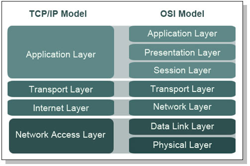
The Network Access Layer of the TCP/IP model combines layers 1 (Physical) and 2 (Data Link) of the OSI model.

The Internet Layer of the TCP/IP model aligns with the Layer 3 (Network) layer of the OSI model. This is where IP addresses and routing live.

The Host-to-Host Transport Layer (sometimes called either “Host-to-Host” or, more commonly, “Transport” alone.It is where applications are addressed on a network, via ports. TCP and UDP are the two Transport Layer protocols of TCP/IP.

The TCP/IP Application Layer combines Layers 5 though 7 (Session, Presentation, and Application) of the OSI model. Most of these protocols use a client-server architecture, where a client (such as ssh) connects to a listening server (called a daemon on UNIX systems) such as sshd.

Here is the mapping between ISO/OSI model and TCP/IP model:

ISO/OSI vs TCP/IP
ISO/OSI vs TCP/IP

Encapsulation takes information from a higher layer and adds a header to it, treating the higher layer information as data.For example, as the data moves down the stack in the TCP/IP model, application layer data is encapsulated in a layer 4 TCP segment. That TCP segment is encapsulated in a Layer 3 IP packet. That IP packet is encapsulated in a Layer 2 Ethernet frame. The frame is then converted into bits at Layer 1 and sent across the local network.

Data, segments, packets, frames, and bits are examples of Protocol Data Units (PDUs).

Physical Layer Protocols and concepts

LAN Physical Network Technologies

  • Bus – All devices are connected to a single cable that’s terminated on both ends. Each node inspects the data as it passes along the bus. Network buses are fragile; should the network cable beak anywhere along the bus, the entire bus will go down.
  • Tree – A tree is also called hierarchical network: a network with a root node, and branch nodes that are at least three levels deep (two levels would make it a star).
  • Ring – A physical ring connects network nodes in a ring: if you follow the cable from node to node, you will finish where you began. In the ring topology, all communication ravels in a single direction around the ring.
  • Star – Each node is connected directly to a central device such as a hub or a switch. Star topology has become the dominant physical topology for LANs.
  • Mesh – All systems are interconnected to provide multiple path to all other resources. In most networks a partial mesh is implemented for only the most critical networks components, such as routers, switches and servers. Meshes heave superior availability and are often used for highly available (HA) server clusters.

Cable and connector types

Cables carry the electrical or light signals that represents data, between devices on a network.Fundamental network cabling terms to understand include EMI, noise, crosstalk, and attenuation.

Electro Magnetic Interference (EMI) is interference caused by magnetism created by electricity. Crosstalk occurs when a signal crosses from one cable to another. Attenuation is the weakening of signal as it travels further from the source.

  • Coaxial cable – consists of single, solid copper-wire-core, surrounded by a plastic insulator, braided-metal shielding, all covered with a plastic sheath. This construction makes the cable very durable and resistant to EMI and Radio Frequency Interference (RFI) signals. Coaxial cables comes in 2 flavors: thick and thin.
  • Twinaxial cable – very similar to coax cables, but it consists of two solid copper-wire cores, rather that a single one. Twinax ix used to achieve hight data (10 Gb) transmission speed over very short distances (10 meter).
  • Twisted-pair cable  are classified by categories according to rated speed. Tighter twisting results in more dampening: a Category 6 designed for gigabit networking have far twitter twisting than a Category 3 fast Ethernet cable.
Category Speed Use
1 1 Mbps Voice Only (Telephone Wire)
2 4 Mbps LocalTalk & Telephone (Rarely used)
3 16 Mbps 10BaseT Ethernet
4 20 Mbps Token Ring (Rarely used)
5 100 Mbps (2 pair) 100BaseT Ethernet
1000 Mbps (4 pair) Gigabit Ethernet
5e 1,000 Mbps Gigabit Ethernet
6 10,000 Mbps Gigabit Ethernet
  • Fiber-optic cable – Fiber Optic network cable (simply called “fiber”) uses light to carry information, which can carry a tremendous amount of information. Fiber can be used to transmit via long distances: past 50 miles, much further than any copper cable. Fiber’s advantages are speed, distance, and immunity to EMI. Disadvantages include cost and complexity.

Network equipement

  • Network Interface Cards (NIC) are used to connect a computer to the  network.
  • Repeater – is a non intelligent device that simply amplifies a signal.A repeater receives bits on one port, and “repeats” them out the other port. The repeater has no understanding of protocols; it simply repeats bits.
  • Hub– A hub is a repeater with more than two ports. It receives bits on one port and repeats them across all other ports.Hubs provide no traffic isolation and have no security: all nodes see all traffic sent by the hub.Hubs are also half-duplex devices: they cannot send and receive simultaneously.Hubs also have one “collision domain”: any node may send colliding traffic with another.

Data Link Layer Protocols and concepts

LAN protocols and transmission methods

Common LAN protocols defines at the Layer 2 level are :

  • Ethernet – is a dominant local area networking technology that transmits network data via frames. It originally used a physical bus topology, but later added support for physical star. Carrier Sense Multiple Access (CSMA) is designed to address collisions.CSMA/CD is used for systems that can send and receive simultaneously, such as wired Ethernet. CSMA/CA (Collision Avoidance) is used for systems such as 802.11 wireless that cannot send and receive simultaneously.
  • ARCNet (Attached Resource Computer Network) – is one of the earliest LAN technology. It is implemented in the star topology by using the coaxial cable.
  • Token-Ring – like ARCNet,  the Token Ring is a legacy LAN technologies. Both pass network traffic via tokens. Possession of a token allows a node to read or write traffic on a network. This solves the collision issue faced by Ethernet: nodes cannot transmit without a token.
  • FDDI (Fiber Distributed Data Interface)  – is another legacy LAN technology, running a logical network ring via a primary and secondary counter-rotating fiber optic ring.
  • ARP (Address Resolution Protocol) – is used to translate between Layer 2 MAC addresses and Layer 3 IP addresses. ARP discovers physical addresses of attached devices by broadcasting ARP query messages on the network segment. IP-address-to-MAC-address translations are then maintained in a dynamic table. ARP maps an IP address to a MAC address and is used to identify a device’s hardware address when only the IP address is known.
  • RARP (Reverse Address Resolution Protocol) – is used by diskless workstations to request an IP address. The system broadcasts a RARP message that that provides the system MAC address and request to be informed of its IP address. RARP maps between a MAC address to an IP address and is used to identify a device’s IP address when only the MAC address is known.

LAN data transmissions are classified as :

  • Unicast  – is one-to-one traffic, such as a client surfing the Web.
  • Multicast – Packets are copied and sent from the source to multiple destination devices by using a special multicast IP address.
  • Broadcast traffic is sent to all stations on a LAN. There are two types of IPv4 broadcast addresses: limited broadcast and directed broadcast. The limited broadcast address is 255.255.255.255. It is “limited” because it is never forwarded across a router, unlike a directed broadcast.

WLAN protocols and transmission methods

Wireless Local Area Networks (WLANs) transmit information via electromagnetic waves (such as radio) or light.

The most common form of wireless data networking is the 802.11 wireless standard, and the first 802.11 standard with reasonable security is 802.11i.

Protocol Release Date Op. Frequency Data Rate (Typical) Data Rate (Max) Range (Indoor)
Legacy 1997 2.4 -2.5 GHz 1 Mbit/s 2 Mbit/s ?
802.11a 1999 5.15-5.35/5.47-5.725/5.725-5.875 GHz 25 Mbit/s 54 Mbit/s ~30 meters (~100 feet)
802.11b 1999 2.4-2.5 GHz 6.5 Mbit/s 11 Mbit/s ~50 meters (~150 feet)
802.11g 2003 2.4-2.5 GHz 11 Mbit/s 54 Mbit/s ~30 meters (~100 feet)
802.11n 2006 (draft) 2.4 GHz or 5 GHz bands 200 Mbit/s 540 Mbit/s ~50 meters (~160 feet)

Another WLAN standard is IEEE standard 802.15 a.k.a Bluetooth. Bluetooth, is a Personal Area Network (PAN) wireless technology, operating in the same 2.4 GHz frequency as many types of 802.11 wireless. Sensitive devices should disable automatic discovery by other Bluetooth devices. The “security” of the discovery relies on the secrecy of the 48-bit MAC address of the Bluetooth adapter. Even when disabled, the Bluetooth devices can be discovered by guessing the MAC address.

WAN technologies and protocols

WAN protocols define how frames are carried across a single data link between two devices.

Point-to-point links – these links provide a single, pre-establish WAN communications path from the customer network, to a remote network.

  • SLIP (Serial Line IP) – was originally developed to support TCP?IP networking over low-speed asynchronous serial lines.
  • PPP (Pont-to-Point protocol) – the successor of SLIP, provides router-to-router and host-to-network connections over synchronous and asynchronous circuits. PPP adds confidentiality, integrity and authentication via point-to-point links.
  • PPTP (Point-to-Point Tunneling Protocol) – tunnels PPP via IP. PPTP doesn’t provides encryption or confidentiality, instead relying on other protocols such as PAP, CHAP and EAP, for security.
  • L2F (Layer 2 Forwarding Protocol) – a tunneling protocol developed by Cisco and used to implement VPNs.

Circuit-switched networks – a dedicated physical circuit path is established, maintained and terminated between the sender and receiver across a carrier network for each communications session. This network type is used extensively in telephone company networks.

  • xDSL (Digital Subscriber Line) – uses existing analog phones lines to deliver high-bandwith connectivity ti remote customers.
  • DOCSIS (Data Over Cable Services Interface Specifications) – is a communication protocol for transmitting high speed data over an existing cable TV system.
  • ISDN (Integrated Services Digital Network) – is a communication protocol that operates over analog phone lines that have been converted to use digital signaling.

Packet-switched networks – devices share bandwidth on communications links to transport packets between a sender and receiver across a carrier network. This type of network is more resilient to errors and congestions than circuit-switched networks.

  • Frame Relay – protocol that provides no error recovery and focuses on speed.
  • X.25 – provided a cost-effective way to transmit data over long distances in the 1970s though 1990s.
  • ATM (Asynchronous Transfer Mode) – is a WAN technology that uses fixed length cels.ATM cells are 53 bytes long with a 5-bytes header and 48-bytes data portion.

Network equipement

Bridges and switches are Layer 2 devices.

A bridge has two ports, and connects network segments together. Each segment typically has multiple nodes, and the bridge learns the MAC addresses of nodes on either side.Traffic sent from two nodes on the same side of the bridge will not be forwarded across the bridge. Traffic sent from a node on one side of the bridge to the other side will forward across.A bridge has two collision domains.

A switch is a bridge with more than two ports. Also, it is best practice to only connect one device per switch port. Otherwise, everything that is true about a bridge is also true about a switch.A switch shrinks the collision domain to a single port. You will normally have no collisions assuming one device is connected per port (which is best practice). Additionally a switch can be used to implement virtual LANs, which logically segregate a network and limit broadcast domains.

Since switches provide traffic isolation, a Networked Intrusion Detection System (NIDS) connected to a 24-port switch will not see unicast traffic sent to and from other devices on the same switch.

Configuring a Switched Port Analyzer(SPAN) port is one way to solve this problem, by mirroring traffic from multiple switch ports to one “SPAN port.” SPAN is a Cisco term; HP switches use the term “Mirror port.” One drawback to using a switch SPAN port is port bandwidth overload.

A TAP (Test Access Port) provides a way to “tap” into network traffic, and see all unicast streams on a network. Taps are the preferred way to provide promiscuous network access to a sniffer or NIDS.

(My) CISSP Notes – Access control

Note: This notes were made using the following books: “CISPP Study Guide” and “CISSP for dummies”.

The purpose of access control is to allow authorized users access to appropriate data and deny access to unauthorized users and the mission and purpose of access control is to protect the confidentiality, integrity, and availability of data. Access control is performed by implementing strong technical, physical and administrative measures. Access control protect against threats such as unauthorized access, inappropriate modification of data, loss of confidentiality.

Basic concepts of access control

CIA triad and his opposite (DAD) – see (My) CISSP Notes – Information Security Governance and Risk Management

A subject is an active entity on a data system. Most examples of subjects involve people accessing data files. However, running computer programs are subjects as well. A Dynamic Link Library file or a Perl script that updates database files with new information is also a subject.

An object is any passive data within the system. Objects can range from databases to text files. The important thing remember about objects is that they are passive within the system. They do not manipulate other objects.

Access control systems provide three essential services:

  • Authentication – determines whether a subject can log in.
  • Authorization – determines what an subject can do.
  • Accountability – describes the ability to determine which actions each user performed on a system.

Access control models

Discretionary Access Control (DAC)

Discretionary Access Control (DAC) gives subjects full control of objects they have been given access to, including sharing the objects with other subjects. Subjects are empowered and control their data.

Standard UNIX and Windows operating systems use DAC for filesystems.

  • Access control list (ACLs) provides a flexible method for applying discretionary access controls. An ACL lists the specific rights and permissions that are assigned to a subject fora given object.
  • Role-Based Access Control (RBAC) is another method for implementing discretionary access controls. RBAC defines how information is accessed on a system based on the role of the subject. A role could be a nurse, a backup administrator, a help desk technician, etc. Subjects are grouped into roles and each defined role has access permissions based upon the role, not the individual.

Major disadvantages of DAC include:

  • lack of centralized administration.
  • dependence of security-conscious resource owners.
  • difficult auditing because of the large volume of log entries that can be generated.

Mandatory Access Control (MAC)

Mandatory Access Control (MAC) is system-enforced access control based on subject’s clearance and object’s labels. Subjects and Objects have clearances and labels, respectively, such as confidential, secret, and top secret.

A subject may access an object only if the subject’s clearance is equal to or greater than the object’s label. Subjects cannot share objects with other subjects who lack the proper clearance, or “write down” objects to a lower classification level (such as from top secret to secret). MAC systems are usually focused on preserving the confidentiality of data.

In MAC, the system determines the access policy.

Common MACs models includes Bell-La Padula, Biba, Clark-Wilson; for more infos about these models please see : (My) CISSP Notes – Security Architecture and Design .

Major disadvantages of MAC control techniques include:

  • lack of flexibility.
  • difficulty in implementing and programming.

Access control administration

An organization must choose the type of access control model : DAC or MAC. After choosing a model, the organization must select and implement different access control technologies and techniques. What is left to work out is how the organization will administer the access control model. Access control administration comes in two basic flavors: centralized and decentralized.

Centralized access models systems maintains user account information in a central location. Centralized access control systems allow organizations to implement a more consistent, comprehensive security policy, but they may not be practical in large organizations.

Exemples  of centralized access control systems and protocols commonly used for authentication of remote users:

  • LDAP
  • RAS – Remote Access Service servers utilize the Point-to-Point Protocol (PPP) to encapsulate IP packets. PPP incorporates the following three authentication protocols: PAP (Password Authentication Protocol), CHAP (Challenge Handshake Authentication Protocol), EAP (Extensible Authentication Protocol).
  • RADIUS – The Remote Authentication Dial In User Service protocol is a third-party authentication system. RADIUS is described in RFCs 2865 and 2866, and uses the User Datagram Protocol (UDP) ports 1812 (authentication) and 1813 (accounting).
  • Diameter is RADIUS’ successor, designed to provide an improved Authentication, Authorization, and Accounting (AAA) framework. RADIUS provides limited accountability, and has problems with flexibility, scalability, reliability, and security. Diameter also uses Attribute Value Pairs, but supports many more: while RADIUS uses 8 bits for the AVP field (allowing 256 total possible AVPs), Diameter uses 32 bits for the AVP field (allowing billions of potential AVPs). This makes Diameter more flexible, allowing support for mobile remote users, for example.
  • TACACS -The Terminal Access Controller Access Control System is a centralized access control system that requires users to send an ID and static (reusable) password for authentication. TACACS uses UDP port 49 (and may also use TCP).

Decentralized access control allows IT administration to occur closer to the mission and operations of the organization. In decentralized access control, an organization spans multiple locations, and the local sites support and maintain independent systems, access control databases, and data. Decentralized access control is also called distributed access control.

Access control defensive categories and types

Access control is achieved throughout an entire et of control which , identified by purpose, include;

  • preventive controls, for reducing risks.
  • detective controls, for identifying violations and incidents.
  • corrective controls, for remedying violations and incidents.
  • deterrent controls, for discouraging violations.
  • recovery controls, for restoring systems and informations.
  • compensating controls, for providing alternative ways of achieving a task.

These access control types can fall into one of three categories: administrative, technical, or physical.

  1. Administrative (also called directive) controls are implemented by creating and following organizational policy, procedure, or regulation.
  2. Technical controls are implemented using software, hardware, or firmware that restricts logical access on an information technology system.
  3. Physical controls are implemented with physical devices, such as locks, fences, gates, security guards, etc.

Preventive controls prevents actions from occurring.

Detective controls are controls that alert during or after a successful attack.

Corrective controls work by “correcting” a damaged system or process. The corrective access control typically works hand in hand with detective access controls.

After a security incident has occurred, recovery controls may need to be taken in order to restore functionality of the system and organization.

The connection between corrective and recovery controls is important to understand. For example, let us say a user downloads a Trojan horse. A corrective control may be the antivirus software “quarantine.” If the quarantine does not correct the problem, then a recovery control may be implemented to reload software and rebuild the compromised system.

Deterrent controls deter users from performing actions on a system. Examples include a “beware of dog” sign:

A compensating control is an additional security control put in place to compensate for weaknesses in other controls.

Here are more clear-cut examples:

Preventive

  • Physical: Lock, mantrap.
  • Technical: Firewall.
  • Administrative: Pre-employment drug screening.

Detective

  • Physical: CCTV, light (used to see an intruder).
  • Technical: IDS.
  • Administrative: Post-employment random drug tests.

Deterrent

  • Physical: “Beware of dog” sign, light (deterring a physical attack).
  • Administrative: Sanction policy.

Authentication methods

A key concept for implementing any type of access control is controlling the proper authentication of subjects within the IT system.

There are three basic authentication methods:

  • something you know – requires testing the subject with some sort of challenge and response where the subject must respond with a knowledgeable answer.
  • something you have – requires that users posses something, such as a token, which proves they are an authenticated user.
  • something you are – is biometrics, which uses physical characteristics as a means of identification or authentication.
  • A fourth type of authentication is some place you are – describes location-based access control using technologies such as the GPS, IP address-based geo location. these controls can deny access if the subject is in incorrect location.

Biometric Enrollment and Throughput

Enrollment describes the process of registering with a biometric system: creating an account for the first time.

Throughput describes the process of authenticating to a biometric system.

Three metrics are used to judge biometric accuracy:

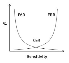
  • the False Reject Rate (FRR) or Type I error- a false rejection occurs when an authorized subject is rejected by the biometric system as unauthorized.
  • the False Accept Rate (FAR) or Type II error- a false acceptance occurs when an unauthorized subject is accepted as valid.
  • the Crossover Error Rate (CER) –  describes the point where the False Reject Rate (FRR) and False Accept Rate (FAR) are equal. CER is also known as the Equal Error Rate (EER). The Crossover Error Rate describes the overall accuracy of a biometric system.
Use CER to compare FAR and FRR

Types of biometric control

Fingerprints are the most widely used biometric control available today.

A retina scan is a laser scan of the capillaries which feed the retina of the back of the eye.

An iris scan is a passive biometric control. A camera takes a picture of the iris (the colored portion of the eye) and then compares photos within the authentication database.

In hand geometry biometric control, measurements are taken from specific points on the subject’s hand: “The devices use a simple concept of measuring and recording the length, width, thickness, and surface area of an individual’s hand while guided on a plate.”

Keyboard dynamics refers to how hard a person presses each key and the rhythm by which the keys are pressed.

Dynamic signatures measure the process by which someone signs his/her name. This process is similar to keyboard dynamics, except that this method measures the handwriting of the subjects while they sign their name.

A voice print measures the subject’s tone of voice while stating a specific sentence or phrase. This type of access control is vulnerable to replay attacks (replaying a recorded voice), so other access controls must be implemented along with the voice print.

Facial scan technology has greatly improved over the last few years. Facial scanning (also called facial recognition) is the process of passively taking a picture of a subject’s face and comparing that picture to a list stored in a database.

Access control technologies

There are several technologies used for the implementation of access control.

Single Sign-On (SSO) allows multiple systems to use a central authentication server (AS). This allows users to authenticate once, and then access multiple, different systems.

SSO is an important access control and can offer the following benefits:

  • Improved user productivity.
  • Improved developer productivity – SSO provides developers with a common authentication framework.
  • Simplified administration.

The disadvantages of SSO are listed below and must be considered before implementing SSO on a system:

  • Difficult to retrofit.
  • Unattended desktop. For example a malicious user could gain access to user’s resources if the user walks away from his machine and leaves in log in.
  • Single point of attack .

SSO is commonly implemented by third-party ticket-based solutions including Kerberos, SESAME or KryptoKnight.

Kerberos is a third-party authentication service that may be used to support Single Sign-On. Kerberos uses secret key encryption and provides mutual authentication of both clients and servers. It protects against network sniffing and replay attacks.

Kerberos has the following components:

  • Principal: Client (user) or service
  • Realm: A logical Kerberos network
  • Ticket: Data that authenticates a principal’s identity
  • Credentials: a ticket and a service key
  • KDC: Key Distribution Center, which authenticates principals
  • TGS: Ticket Granting Service
  • TGT: Ticket Granting Ticket
  • C/S: Client Server, regarding communications between the two

Kerberos provides mutual authentication of client and server.Kerberos mitigates replay attacks (where attackers sniff Kerberos credentials and replay them on the network) via the use of timestamps.

The primary weakness of Kerberos is that the KDC stores the plaintext keys of all principals (clients and servers). A compromise of the KDC (physical or electronic) can lead to the compromise of every key in the Kerberos realm. The KDC and TGS are also single points of failure.

SESAME is Secure European System for Applications in a Multi-vendor Environment, a single sign-on system that supports heterogeneous environments.

“SESAME adds to Kerberos: heterogeneity, sophisticated access control features, scalability of public key systems, better manageability, audit and delegation.”20 Of those improvements, the addition of public key (asymmetric) encryption is the most compelling. It addresses one of the biggest weaknesses in Kerberos: the plaintext storage of symmetric keys.

Assessing access control

A number of processes exist to assess the effectiveness of access control. Tests with a narrower scope include penetration tests, vulnerability assessments, and security audits.

Penetration tests

Penetration tests may include the following tests:

  • Network (Internet)
  • Network (internal or DMZ)
  • Wardialing
  • Wireless
  • Physical (attempt to gain entrance into a facility or room)

A zero-knowledge (also called black box) test is “blind”; the penetration tester begins with no external or trusted information, and begins the attack with public information only.

A full-knowledge test (also called crystal-box) provides internal information to the penetration tester, including network diagrams, policies and procedures, and sometimes reports from previous penetration testers.

Penetration testers use the following methodology:

  • Planning
  • Reconnaissance
  • Scanning (also called enumeration)
  • Vulnerability assessment
  • Exploitation
  • Reporting

Vulnerability testing

Vulnerability scanning (also called vulnerability testing) scans a network or system for a list of predefined vulnerabilities such as system misconfiguration, outdated software, or a lack of patching. A vulnerability testing tool such as Nessus (http://www.nessus.org) or OpenVAS (http://www.openvas.org) may be used to identify the vulnerabilities.

Security audit

A security audit is a test against a published standard. Organizations may be audited for PCI (Payment Card Industry) compliance, for example. PCI includes many required controls, such as firewalls, specific access control models, and wireless encryption.

Security assessments

Security assessments view many controls across multiple domains, and may include the following:

  • Policies, procedures, and other administrative controls
  • Assessing the real world-effectiveness of administrative controls
  • Change management
  • Architectural review
  • Penetration tests
  • Vulnerability assessments
  • Security audits

(My) CISSP Notes – Business Continuity and Disaster Recovery Planning

Note: This notes were made using the following books: “CISPP Study Guide” and “CISSP for dummies”.

Business Continuity and Disaster Recovery Planning is an organization’s last line of defense: when all other controls have failed, BCP/DRP is the final control that may prevent drastic events such as injury, loss of life, or failure of an organization.

An additional benefit of BCP/DRP is that an organization that forms a business continuity team, and conducts a thorough BCP/DRP process, is forced to view the organization’s critical processes and assets in a different, often clarifying, light. Critical assets must be identified and key business processes understood. Standards are employed. Risk analysis conducted during a BCP/DRP plan can lead to immediate mitigating steps.

BCP

The overarching goal of a BCP is for ensuring that the business will continue to operate before, throughout, and after a disaster event is experienced. The focus of a BCP is on the business as a whole, and ensuring that those critical services that the business provides or critical functions that the business regularly performs can still be carried out both in the wake of a disruption as well as after the disruption has been weathered.

Business Continuity Planning provides a long-term strategy for ensuring that continued successful operation of an organization in spite of inevitable disruptive events and disasters.

BCP deals with keeping business operations running, perhaps in other location or using different tools and processes, after the disaster has struck.

DRP

The DRP provides a short-term plan for dealing with specific IT-oriented disruptions. The DRP focuses on efficiently attempting to mitigate the impact of a disaster and the immediate response and recovery of critical IT systems in the face of a significant disruptive event.The DRP does not focus on long-term business impact in the same fashion that a BCP does. DRP deals with restoring normal business operations after the disaster takes place.

These two plans, which have different scopes, are intertwined. The Disaster Recovery Plan serves as a subset of the overall Business Continuity Plan, because a BCP would be doomed to fail if it did not contain a tactical method for immediately dealing with disruption of information systems.

Defining disastrous events

The three common ways of categorizing the causes for disasters are as to whether the threat agent is natural, human, or environmental in nature.

  • Natural disasters – fires and explosions, earthquakes, storms, floods, hurricanes, tornadoes, landslices, tsunamis, pandemics
  • Human disasters (intentional or unintentional threat) – accidents, crime and mischief, war and terrorism, cyber attacks/cyber warfare, civil disturbance
  • Environmental disasters – this class of threat includes items such as power issues (blackout, brownout, surge, spike), system component or other equipment failures, application or software flaws.

Though errors and omissions are the most common threat faced by an organization, they also represent the type of threat that can be most easily avoided.

The safety of an organization’s personnel should be guaranteed even at the expense of efficient or even successful restoration of operations or recovery of data.

Recovering from a disaster

The general process of disaster recovery involves responding to the disruption; activation of the recovery team; ongoing tactical communication of the status of disaster and its associated recovery; further assessment of the damage caused by the disruptive event; and recovery of critical assets and processes in a manner consistent with the extent of the disaster.

  • Respond – In order to begin the disaster recovery process, there must be an initial response that begins the process of assessing the damage. The initial assessment will determine if the event in question constitutes a disaster.
  • Activate Team – If during the initial response to a disruptive event a disaster is declared, then the team that will be responsible for recovery needs to be activated.
  • Communicate – After the successful activation of the disaster recovery team, it is likely that many individuals will be working in parallel on different aspects of the overall recovery process. In addition to communication of internal status regarding the recovery activities, the organization must be prepared to provide external communications, which involves disseminating details regarding the organization’s recovery status with the public.
  • Assess – A more detailed and thorough assessment will be done by the, now activated, disaster recovery team. The team will proceed to assess the extent of damage to determine the proper steps to ensure the organization’s mission is fulfilled.
  • Reconstitution   – The primary goal of the reconstitution phase is to successfully recover critical business operations either at primary or secondary site.

BCP/DRP Project elements

A BCP project typically has four components: Scope determination, business impact assessment, identify preventive controls and implementation.

BCP Scope

The success and effectiveness of a BCP depends greatly on whether senior management and the project team properly defines the scope. Specific questions will need to be asked of the BCP/DRP planning team like “What is in and out of scope of this plan”.

Business impact assessment (BIA)

The BIA describes the impact that a disaster is expected to have on business operations. Any BIA should contains the following tasks:

  • Perform an vulnerability Assessment – The goal of the vulnerability assessment is to determine the impact of the loss of a critical business function.
  • Perform a critically assessmentThe team members need to estimate the duration of a disaster event to effectively prepare the critically assessment. Project team members needs to consider the impact of a disruption based on the length of time that a disasters impairs critical business functions.
  • Determine the Maximum Tolerable DowntimeThe primary goal of the BIA is to determine the Maximum Tolerable Downtime (MTD), also known as Maximum Tolerable Period Of Disruption (MTPD) for a specific IT asset. MTD is the maximum period of time that a critical business function can be inoperative before the company incurs significant and log-lasting damage.
  • Establish recovery targetsThese targets represent the period of time from the start of a disaster until critical processes have resumes functioning. Two primary recovery targets are established for each business process: Recovery Time Objective (RTO) and Recovery Point Objective(RPO).RTO is the maximum period of time in which a business prices must be restored after a disaster. The RTO is also called the system recovery time.

    RPO is the maximum period of time in which data might be lost if a disaster strikes. The RPO represents the maximum acceptable amount of data/work loss for a given process because of a disaster or disruptive event.

  • Determine ressource requirements – This portion of the BIA is a listing of the resources that an organization needs in order to continue operating each critical business function.

Identify preventive controls

Preventive controls prevent disruptive events from having an impact. The BIA will identify some risks which might be mitigated immediately. Once the BIA is complete, the BCP team knows the Maximum Tolerable Downtime. This metric, as well as others including the Recovery Point Objective and Recovery Time Objective, are used to determine the recovery strategy.

Once an organization has determined its maximum tolerable downtime, the choice of recovery options can be determined. For example, a 10-day MTD indicates that a cold site may be a reasonable option. An MTD of a few hours indicates that a redundant site or hot site is a potential option.

  • A redundant site is an exact production duplicate of a system that has the capability to seamlessly operate all necessary IT operations without loss of services to the end user of the system.
  • A hot site is a location that an organization may relocate to following a major disruption or disaster.It is important to note the difference between a hot and redundant site. Hot sites can quickly recover critical IT functionality; it may even be measured in minutes instead of hours. However, a redundant site will appear as operating normally to the end user no matter what the state of operations is for the IT program.
  • A warm sitehas some aspects of a hot site, for example, readily-accessible hardware and connectivity, but it will have to rely upon backup data in order to reconstitute a system after a disruption.An organizations will have to be able to withstand an MTD of at least 1-3 days in order to consider a warm site solution.
  • A cold site is the least expensive recovery solution to implement. It does not include backup copies of data, nor does it contain any immediately available hardware.
  • Reciprocal agreements are a bi-directional agreement between two organizations in which one organization promises another organization that it can move in and share space if it experiences a disaster.
  • Mobile sites are “datacenters on wheels”: towable trailers that contain racks of computer equipment.

As discussed previously, the Business Continuity Plan is an umbrella plan that contains others plans. In addition to the Disaster recovery plan, other plans include the Continuity of Operations Plan (COOP), the Business Resumption/Recovery Plan (BRP), Continuity of Support Plan, Cyber Incident Response Plan, Occupant Emergency Plan (OEP), and the Crisis Management Plan (CMP).

The Business Recovery Plan (also known as the Business Resumption Plan) details the steps required to restore normal business operations after recovering from a disruptive event. This may include switching operations from an alternate site back to a (repaired) primary site.

The Continuity of Support Plan focuses narrowly on support of specific IT systems and applications. It is also called the IT Contingency Plan, emphasizing IT over general business support.

The Cyber Incident Response Plan is designed to respond to disruptive cyber events, including network-based attacks, worms, computer viruses, Trojan horses.

The Occupant Emergency Plan(OEP) provides the “response procedures for occupants of a facility in the event of a situation posing a potential threat to the health and safety of personnel, the environment, or property”.  This plan is facilities-focused, as opposed to business or IT-focused.

The Crisis Management Plan(CMP) is designed to provide effective coordination among the managers of the organization in the event of an emergency or disruptive event. A key tool leveraged for staff communication by the Crisis Communications Plan is the Call Tree, which is used to quickly communicate news throughout an organization without overburdening any specific person. The call tree works by assigning each employee a small number of other employees they are responsible for calling in an emergency event.

Implementation

The implementation phase consists in testing, training and awareness and continued maintenance.

In order to ensure that a Disaster Recovery Plan represents a viable plan for recovery, thorough testing is needed. There are different types of testing:

  • The DRP Review is the most basic form of initial DRP testing, and is focused on simply reading the DRP in its entirety to ensure completeness of coverage.
  • Checklist(also known as consistency) testing lists all necessary components required for successful recovery, and ensures that they are, or will be, readily available should a disaster occur.Another test that is commonly completed at the same time as the checklist test is that of the structured walkthrough, which is also often referred to as a tabletop exercise.
  • A simulation test, also called a walkthrough drill (not to be confused with the discussion-based structured walkthrough), goes beyond talking about the process and actually has teams to carry out the recovery process. A pretend disaster is simulated to which the team must respond as they are directed to by the DRP.
  • Another type of DRP test is that of parallel processing. This type of test is common in environments where transactional data is a key component of the critical business processing. Typically, this test will involve recovery of critical processing components at an alternate computing facility, and then restore data from a previous backup. Note that regular production systems are not interrupted.
  • Arguably, the most high fidelity of all DRP tests involves business interruption testing. However, this type of test can actually be the cause of a disaster, so extreme caution should be exercised before attempting an actual interruption test.Once the initial BCP/DRP plan is completed, tested, trained, and implemented, it must be kept up to date.BCP/DRP plans must keep pace with all critical business and IT changes.Business continuity and disaster recovery planning are a business’ last line of defense against failure. If other controls have failed, BCP/DRP is the final control. If it fails, the business may fail.

    A handful of specific frameworks are worth discussing, including NIST SP 800-34, ISO/IEC-27031, and BCI.